RE102 Radiated Emissions
Overview
Purpose
The MIL-STD-461 RE102 test method defines how to measure radiated emission noise from electric units and their electrical cables. Most people believe that EMI comes from the unit itself, but most radiated emissions failures are due to currents on the cables, which are excellent radiators. It is extremely important to document the shielding requirements of your unit cables and to test how you fly.
The RE102 test has similarities to the automotive test method CISPR 25 but is significantly different from the general commercial testing standards including ANSI C63.4 and CISPR 32.
RE102 Limit Line
The standard RE102 limit line for aircraft and spacecraft applications from 10 kHz to 18 GHz is shown below when tested at 1 meter from the setup. For comparison, FCC testing requires conducted emissions testing from 30 MHz to a maximum of 40 GHz with distances of 3 meters and 10 meters. The limit is given as dBµV/m which is calculated from the linear electric field as:
20*log10(E[µV/m] / 1 µV/m)
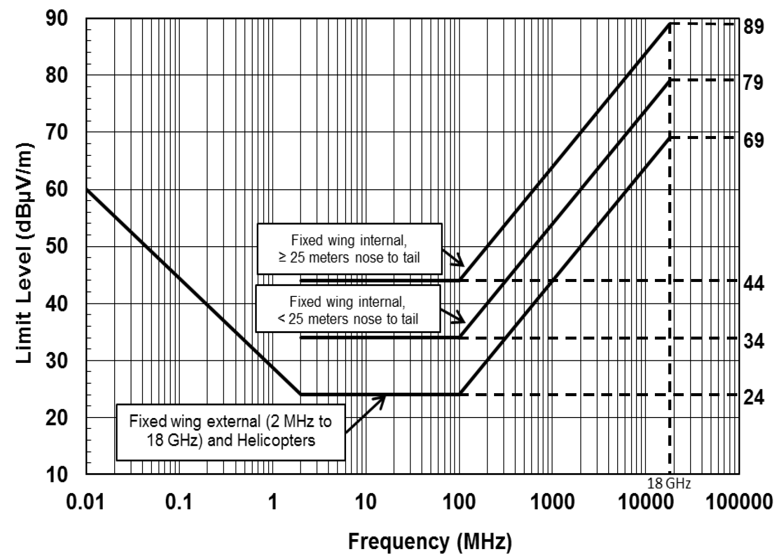
Keep in mind, the standard limits given in MIL-STD-461G are just a starting point and most programs require tailoring of the RE102 limits following MIL-STD-464. It is very common to include receive band notches:
- Lower GNSS band: 1164–1300 MHz
- Upper GNSS band: 1559–1610 MHz
- S-band communications: 2200–2400 MHz
Whether the unit is placed inside the satellite Faraday cage will affect the required RE102 limit for these receive band notches, but the notches generally range from 30 to 50 dBµV/m. A common practice for spacecraft EMC designers is to set a flat limit of 70 or 80 dBµV/m across the 10 kHz to 18 GHz range and add the receive band notches.
RE102 Test Setup
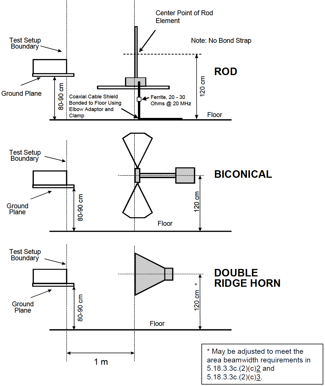
The diagrams of the general test setup and the RE102 antenna positioning are shown below. This is similar to the CE102 setup except that the LISN measurement ports are terminated.
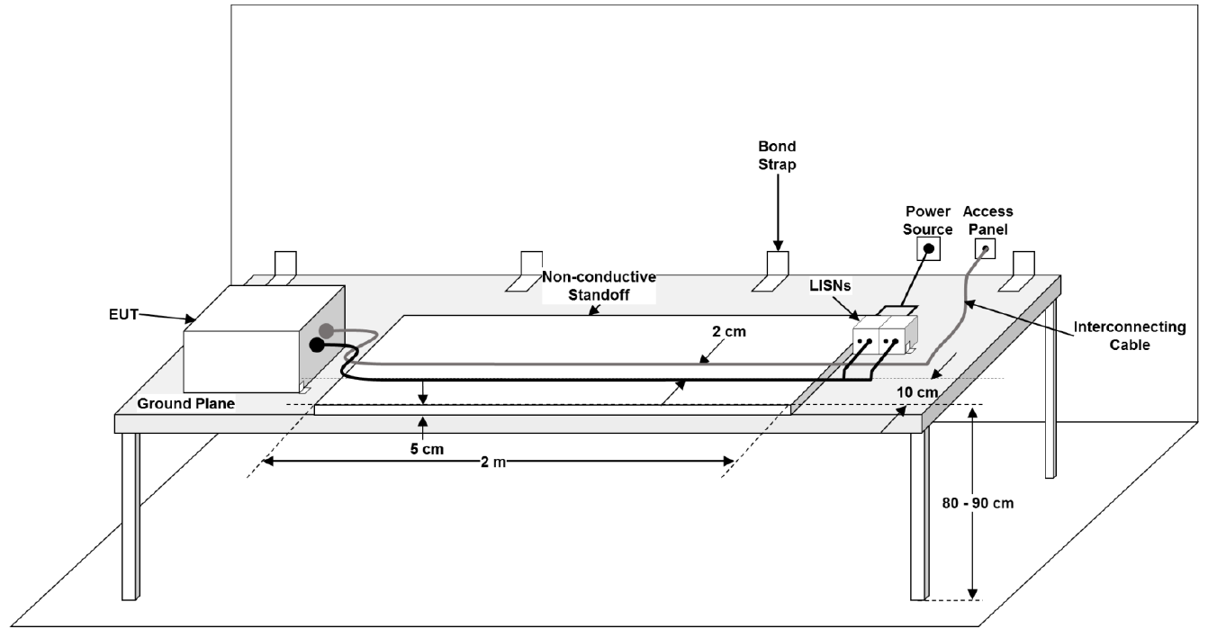
The standard RE102 setup assumes that power will be unshielded and that the power and communication signals will be routed separately, but this is often not the case for 28 VDC applications where the power and communications are routed together inside an overbraid shield. If you have a shielded harness and break out the power to the LISN, then the shield will be broken and RF currents allowed to penetrate the shield barrier.
In this case, it is best to route the harnesses through the chamber bulkhead connector and terminate the power leads to a LISN outside the test chamber. This will maintain the overbraid shield and prevent RF currents from penetrating the shield barrier.
Design and Analysis
General Approach
Compliance to RE102 can be achieved using a combination of simulation and pre-compliance bench testing of a prototype. This section covers considerations in the steps involved.
RE102 Simulations
For simulations, radiated emission estimations are performed in several steps. Each subsequent step increases the accuracy of the emissions model. When simulations are required, circuit simulations with PSpice are preferred because they give deep understanding of the emissions and can be performed much faster than a full 3D electromagnetic solver.
Step 1 — Survey the unit for clocks and switching frequencies
Every PCB and unit should be reviewed and the frequency, rise/fall times, and modulation of the clocks and data communication lines recorded. Focus on high-speed interfaces or clocks including internally generated PLL clocks. Rise/fall times determine the highest harmonic frequency and can be estimated from datasheets or IBIS models.
The Goal: Identify likely emission sources and their frequencies.
Step 2 — Create an EMC grounding diagram of your PCB
Understanding how return current flows is central to controlling radiated emissions. Identify:
- Potential current return paths of external cabling
- Potential internal return paths between PCB reference planes
Include filtering, shielding, intentional and parasitic capacitances.
The Goal: Identify where currents can flow from a big-picture view.
Step 3 — Perform harness emissions simulations
Most radiated emissions problems come from common mode currents on cables. The goal is to:
- Quantify the current on the cables
- Estimate radiated emissions from those currents
Construct a coupling model from the grounding diagram. Include partial inductance, parasitic capacitance to chassis, and cable shielding. Use the EMI Sleuth RE102 cable emission estimator in PSpice.
The Goal: Quantify radiated emissions from cables and determine if filtering or shielding is required.
Step 4 — Perform direct PCB emissions simulations
Focus on exposed traces and IC package leads of high-risk sources. Buried traces between ground planes with stitching vias are poor radiators. Use IBIS driver models plus the EMI Sleuth RE102 emission estimator.
If emissions exceed limits, consider a metal chassis and estimate shielding effectiveness.
The Goal: Determine enclosure shielding requirements.
Caution
- Minimize loop area of return current paths
- Add stitching vias generously
- Avoid split ground planes — they create large loop areas and patch antennas
- Partition circuits by type (power, digital, analog)
- Use isolation circuits when shared ground planes are not acceptable
RE102 Pre-Compliance Testing
Testing your product before official EMC testing is key to passing the first time. Simulations identify risks early, but simplified models must be validated with bench testing.
The hardest part is controlling environmental noise pickup. Ideally use a shielded room, but portable fabric EMI chambers can provide 40–80 dB shielding.
Recommendations for pre-compliance testing from 30 MHz to 3 GHz:
Step 1 — Get test equipment
You will need:
- Spectrum analyzer or EMI receiver
- Biconical antenna (30 MHz–1 GHz)
- Horn antenna (1–3 GHz minimum)
- RF current probe (ideally rated to 500 MHz or more)
- Realistic test cables
- LISN (if appropriate)
The Goal: Acquire or build the right tools for pre-compliance testing.
Step 2 — Get a ground plane
Use a conductive table (aluminum sheet on wood). Bond the ground plane to the equipment grounding conductor. Add a bulkhead connector at the table edge.
The Goal: Make your pre-compliance setup match MIL-STD-461 as closely as possible.
Step 3 — Test with a current probe
RF current probes are highly sensitive and ideal for measuring cable emissions. Sweep the probe along the cable while using peak detect + max hold on the analyzer. Convert current to electric field using the EMI Sleuth RE102 cable radiator.
Caution:
- Limited maximum frequency
- Sensitive to harness position (standing waves)
- Measures current, not field — requires conversion
The Goal: Measure common mode cable currents and determine if filtering or shielding is required.
Step 4 — Test with antennas
Antennas outside a chamber may pick up noise. Focus on frequencies above the current probe range. Use three measurement cases:
- Noise floor with EUT off at 1 m
- Emissions at 1 m with EUT on
- Emissions at 0.33 m with EUT on
EUT emissions should be 10–20 dB higher at 0.33 m. No change indicates emissions from support equipment.
The Goal: Measure radiated emissions from electronics and cables and identify fixes before official testing.
Need Help?
If the steps above seem daunting or you run into problems along the way, then please reach out to EMI Sleuth for help in closing the analysis, testing on the bench and getting the unit passing.