Overview
Purpose
The MIL-STD-461 CS101 test injects voltage noise into the power lead of electronic units to ensure the unit is not susceptible to steady-state electronic noise on the shared power bus. It also checks sensitivity to power quality effects including harmonic distortion of AC power.
Frequency coverage comparison:
| Test | Frequency Range | Comment |
|---|---|---|
| CE101 | 30 Hz - 20 kHz | |
| CE102 | 10 kHz – 10 MHz | Often extended to 50 MHz |
| CS101 | 30 Hz – 150 kHz | <- Discussed here |
| CS114 | 10 kHz – 200 MHz | Includes power line noise at high frequency |
CS101 tests direct voltage noise on the bus; CS114 simulates inductive noise coupling from adjacent power cables.
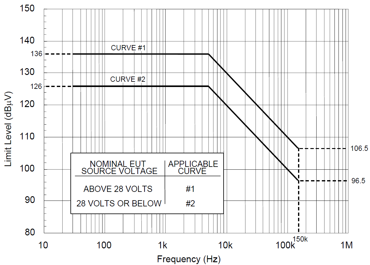
CS101 Limit Line
The limit is expressed as a voltage from 30 Hz to 150 kHz with a relaxation at 5 kHz. A peak power limit of 80 W injected into the power line also applies.
Levels are in RMS: 126 dBµV = 2 Vrms = 2.828 Vpk
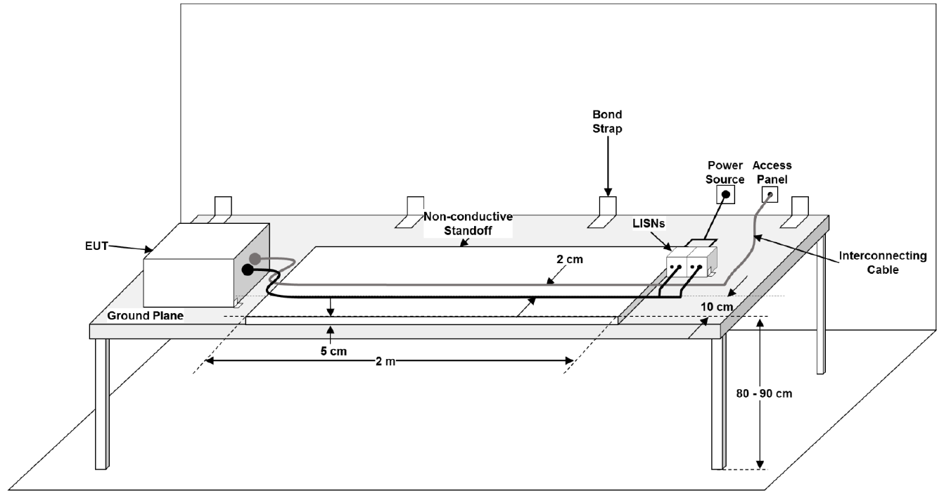
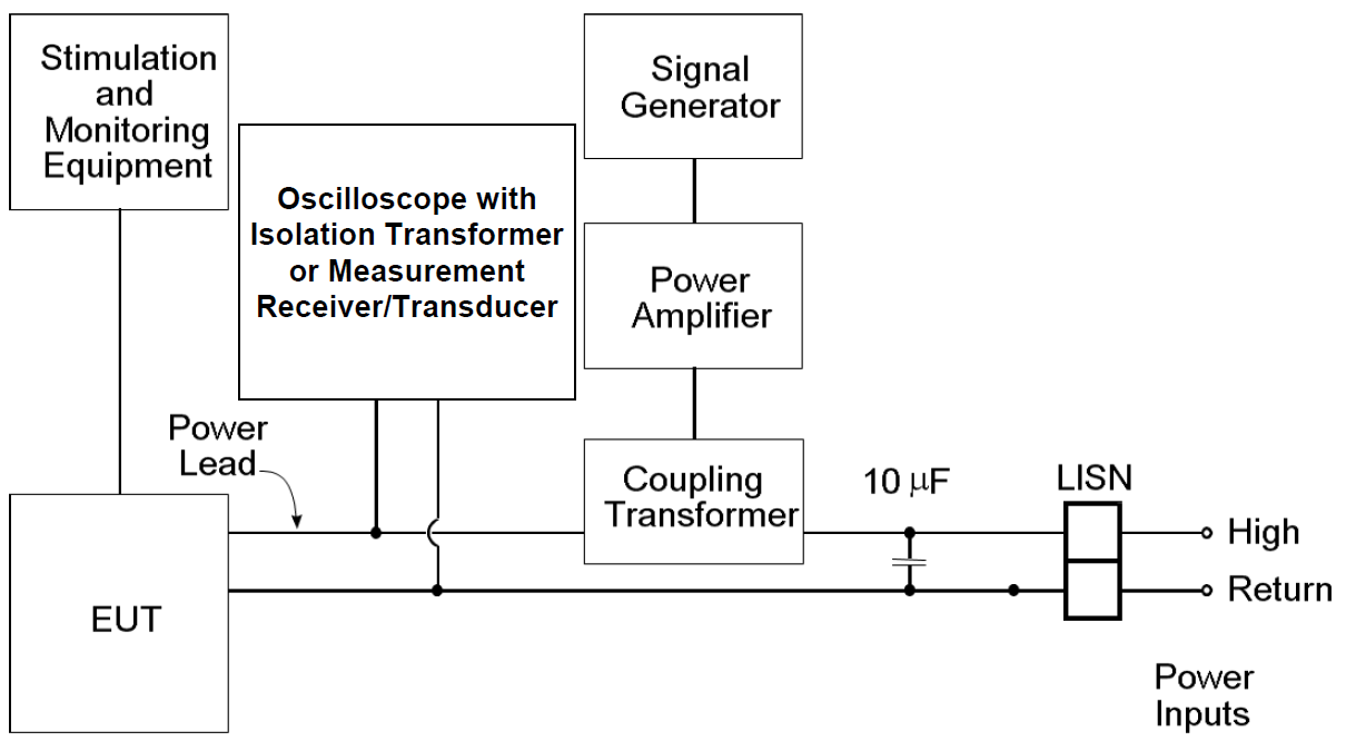
Test Setup
The CS101 setup is similar to CE102 with the addition of:
- Signal injection transformer
- 10 µF line-to-return capacitor
- Oscilloscope to monitor injected voltage
Use differential probes to monitor line voltage — avoid isolation transformers on oscilloscopes due to grounding requirements.
Design and Analysis
General Approach
CS101 is one of the easiest MIL-STD-461 tests to pass if a little design effort is made. This test is easy to simulate because the frequencies are low and CS101 only applies to the power supply line input. Three key guidelines are:
Step 1 — The power supply input voltage range must be wide enough
This test temporarily shifts the voltage seen by the input power supply up and down several volts. During testing, the input voltage is set to the minimum and maximum voltage across the rated voltage range of the EUT. The operational voltage range must be large enough to accept this additional positive and negative voltage injected on top of the supply. Otherwise, the supply can shut down due to under-voltage conditions or be damaged due to over-voltage conditions.
Step 2 — EMI filter resonances should be damped
If resonances occur in the EMI filter, then the CS101 injected voltage can be multiplied several times due to resonances. This may cause under-voltage or over-voltage conditions and lead to shutdown or damage of the power supply. Adding damping resistors to the filter may be required. Damping resistances usually help with system power quality requirements because resonances in the CS101 frequency range may cause instability in converters.
Step 3 — Isolate the power supply input or use chassis power return
Isolating the input power lines from chassis ground and all signal references is best practice. However, sometimes a non-isolated power supply (such as a 28 V to 5 V buck converter) is attempted due to significant size, weight and power (SWaP) benefits. This can work if you are using a DC chassis power return and implement appropriate grounding and bonding rules at the system level.
Attempting to use a non-isolated DC power supply input in the EUT will introduce susceptibility and emissions concerns for every non-isolated interface on the unit.
CS101 Simulations
I recommend getting the CE102 simulation running first in PSpice because emissions requirements are usually more difficult to meet. The CS101 simulation will build upon the CE102 simulation with the following steps:
Step 1 — Add the injection transformer and 10 µF capacitor
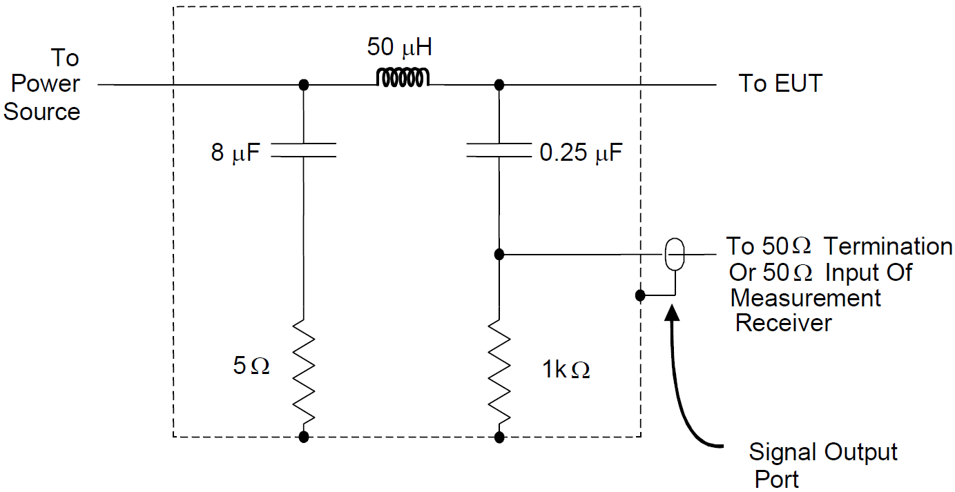
The injection transformer must be added on the power input line but can be modeled as an ideal 1 VAC voltage source. The capacitor should be added at the LISN and an ideal capacitor model can be used.
Step 2 — Remove the switch mode supply model
Most of the switch mode power supply model may be removed. It is important to leave the input capacitor bank to the switch converter because that will significantly affect the CS101 response, including resonances.
Step 3 — Create an AC simulation
The CS101 simulation should be an AC sweep from 30 kHz to 10 MHz with a minimum number of points per decade of 462 to give a frequency resolution of 0.5% or better, which is double the accuracy required by testing. The voltage should be probed at the input capacitor bank of the converter.
Step 4 — Perform post processing and iterations
Once the simulation is complete, export the output to a CSV file. Copy and paste the probe voltage data into a CS101 post-processing Excel template to scale to the specified limit line. The pass–fail criteria is typically based on the operational voltage range. I recommend showing a minimum design margin of 6 dB in a CS101 analysis. If exceedances are observed due to resonances, then damping resistance may need to be added to the EMI filter (usually in series with capacitors). If changes are made, then the CE102 simulation should be updated.
This may take several iterations, but the design needs to close for both CS101 and CE102.
CS101 Pre-Compliance Testing
Bench testing for CS101 should follow the same CE102 setup but with the injection transformer, 10 µF capacitor, and monitor oscilloscope added. The unit should be monitored for correct behavior while the injection level is increased in 1% frequency steps (232 points minimum per decade). Automating this testing with scripting is recommended.
Step 1 — Transformer and driver
Most linear isolation transformers designed for 60 Hz power applications can work as an injection transformer. A standard function generator can be used to generate the waveform, but it should be buffered with a power amplifier. Off-the-shelf amplifiers are readily available, but a power BJT push–pull circuit can be built if needed.
Step 2 — Return line
CS101 only requires testing of the input power lines, and power returns are not required to be tested. I recommend testing the power return lines as well in pre-compliance testing, especially if a non-isolated power supply is used but not chassis power return.
Step 3 — Design margin
The only way to quantify design margin with bench testing of CS101 is by over-testing. This may not be appropriate for all designs and damage may occur if any parts are overstressed. Also, CS101 can take a long time to step through all frequencies, so gradually increasing the injection level is generally not feasible.
I recommend bench testing at the specified CS101 injection level to verify compliance, but a simulation design margin of 6 dB or more is sufficient to ensure a robust design.
Need Help?
If the steps above seem daunting or you run into problems along the way, then please reach out to EMI Sleuth for help in closing the analysis, testing on the bench and getting the unit passing.