Overview
Purpose
The MIL-STD-461 CE102 test method measures conducted emission noise on the power leads of electronic units. Unlike FCC testing which only applies to AC power inputs, CE102 applies to both AC and DC power inputs. The purpose is to ensure a high quality of power supplied by the bus and limit noise seen by connected units. Because power lines are typically unshielded, it also limits electric field coupling to nearby sensitive analog circuits.
Frequency coverage comparison:
| Test | Frequency Range | Comment |
|---|---|---|
| CE101 | 30 Hz - 20 kHz | |
| CE102 | 10 kHz – 10 MHz | <- Discussed here |
| CS101 | 30 Hz – 150 kHz | |
| CS114 | 10 kHz – 200 MHz | Includes power line noise at high frequency |
CE102 Limit Line
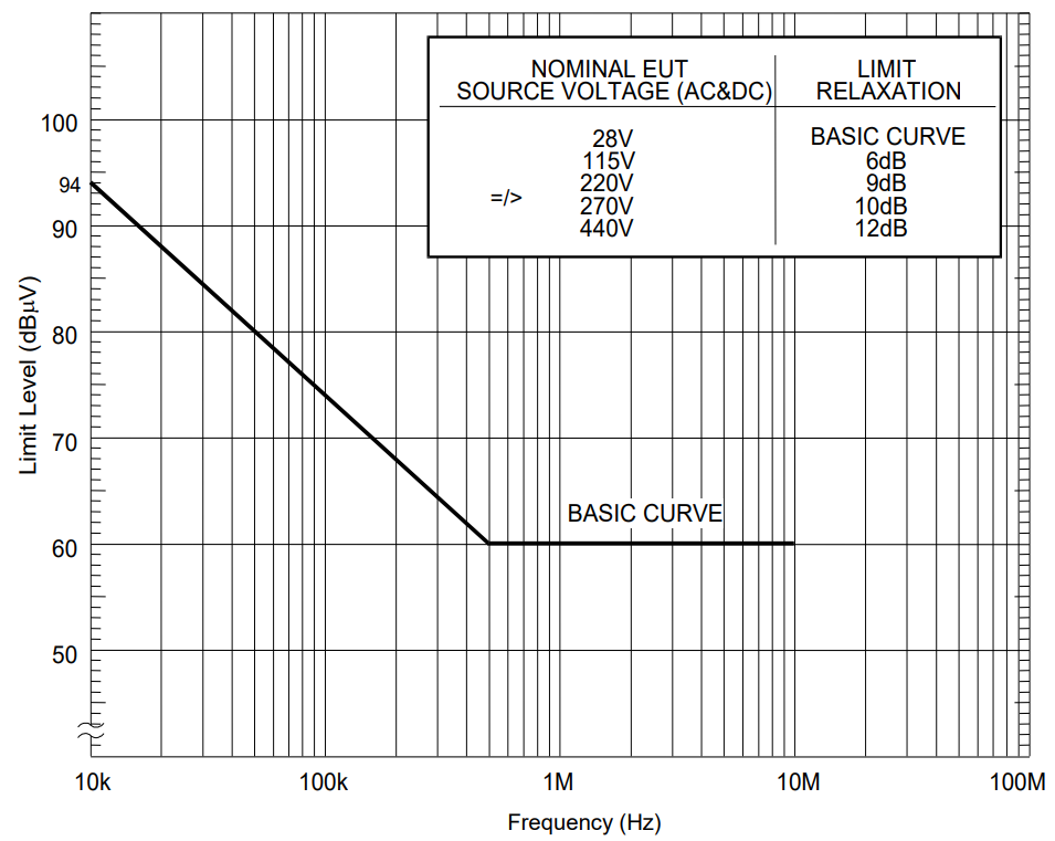
The standard CE102 limit line for AC and DC powered units with a 50 µH LISN is defined for noise from 10 kHz to 10 MHz. For comparison, FCC testing covers 150 kHz to 30 MHz. Satellite EMC requirements often extend the 60 dBµV limit to 20 or 50 MHz.
Note:
All limit levels are RMS —> 60 dBµV = 1 mVrms = 1.414 mVpk
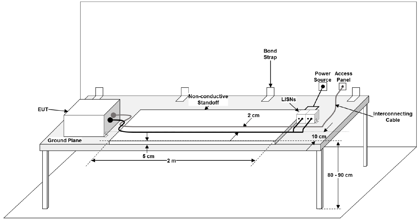
CE102 Test Setup
The standard setup requires:
- Test harnesses minimum 3 meters long
- Power and communication lines to separate connectors with minimum 2 cm separation
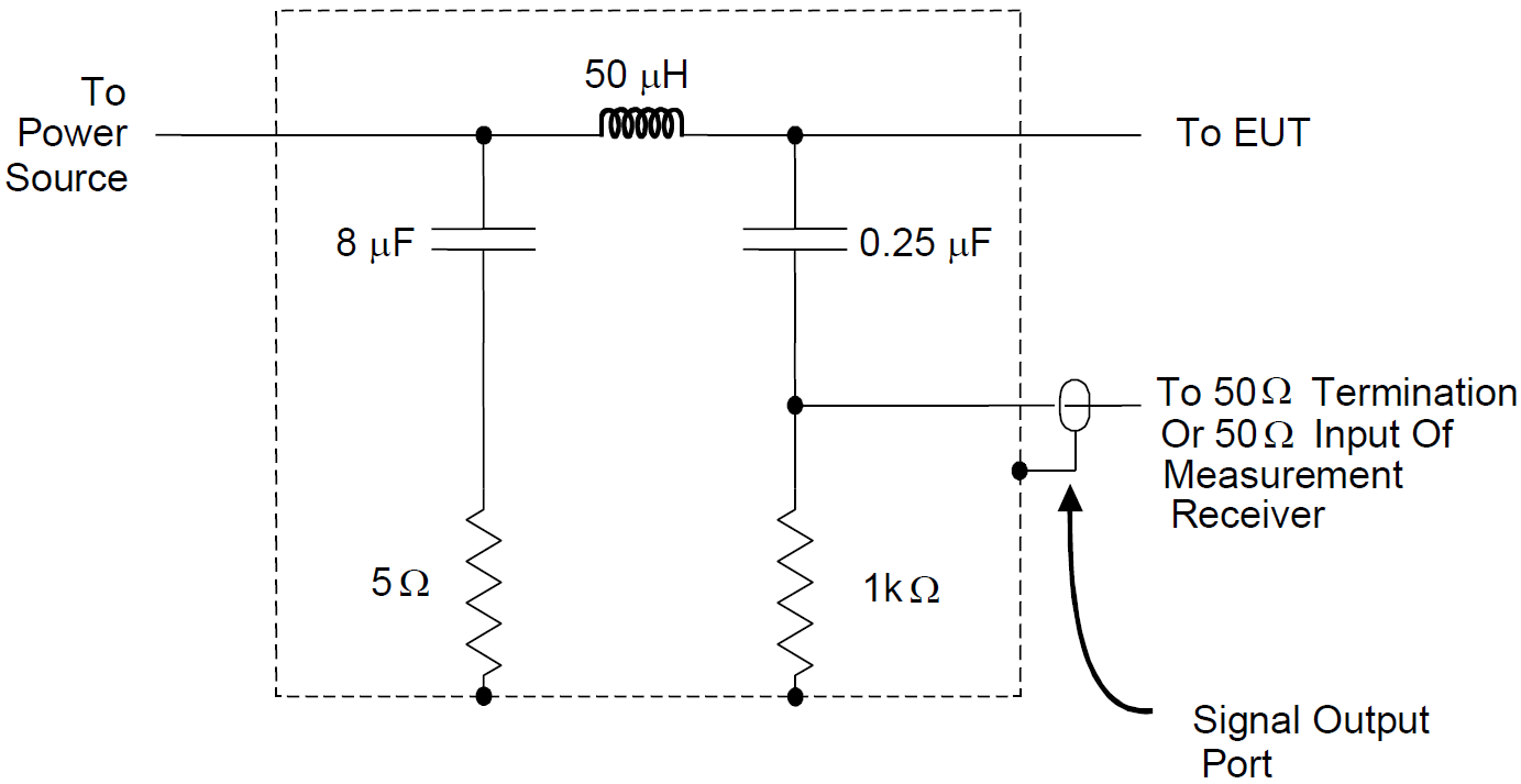
- 50 µH LISN connected per the standard diagram
- Measurement receiver (spectrum analyzer or oscilloscope for pre-compliance)
Design and Analysis
General Approach
Compliance to CE102 can be achieved using a combination of simulation and pre-compliance bench testing of a prototype.
CE102 PSpice Simulations
Step 1 — Generate a source model
The primary source of power line noise is the input switch converter (often a flyback converter). The source model should include:
- Transformer with parasitics (drain-source capacitance, primary-to-secondary winding capacitance, leakage inductance)
- FET switch and snubber circuits
- Output load modeled as a resistor
This step is often the most difficult and time-consuming but also the most important.
Step 2 — Add input power, LISN, and connecting cables
- Ideal linear component models are acceptable for LISN components
- The 2-meter connecting cable should be modeled as a lumped-element multiconductor transmission line
Step 3 — Add filter components
- Line-to-ground (Y-rated) and line-to-return (X-rated) capacitors — include parasitic inductance and resistance
- Common-mode chokes and inductors — use manufacturer models where available
- Account for DC bias effects on ceramic capacitors and inductor saturation
Step 4 — Perform the simulation
- Time domain simulation with minimum step size based on maximum frequency
- Ignore data until after steady-state behavior is established
- Simulation time: 0.1 to 1 ms (integer number of switching cycles to prevent FFT errors)
Step 5 — Post processing
- Probe LISN line and return port voltage; perform FFT in PSpice
- Export to CSV and import into your CE102 post-processing template
- Scale to the limit line and assess design margin (recommend ≥ 6 dB)
CE102 Pre-Compliance Testing
It is critical that a prototype of the design be tested as early as possible. This will validate the simulation and give good confidence in passing the formal EMC qualification testing. If you chose not to perform a simulation of the CE102 noise, then this pre-compliance testing is even more critical.
Here are some tips on pre-compliance EMC testing that I’ve learned over the years:
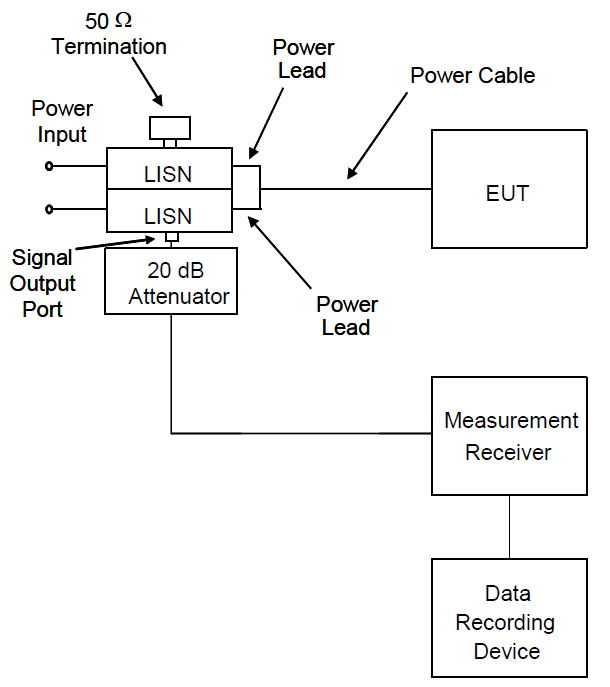
Step 1 — Get or make a LISN
Many affordable LISNs are available, and I highly recommend buying a couple. You will need at least two, one for the input line and one for the power return. If you can’t buy the LISNs due to budget or procurement restrictions, then make your own. Be sure to select components that do not have resonances in your measurement frequency. LISNs are among the easiest EMC instruments to design and make at reasonable current levels.
Not having a LISN is no excuse to skip conducted emissions testing!
Step 2 — Get a ground plane
The equipment under test and cables should be placed on top of a ground plane. This is important to keep the grounding representative of the final testing and helps reduce nearby RF noise from coupling on the cables. If you don’t have a metal table, then get a roll of aluminum skirting or sheet metal from a hardware store and lay it out on a wooden table.
Step 3 — Use an oscilloscope
If you have a spectrum analyzer then feel free to use it. However, those can be hard to find, and an oscilloscope can give similar results. Oscilloscopes also have a built-in math function that can calculate the common mode and differential mode noise directly. Keep in mind that the oscilloscope channel must be 50 Ohm terminated and the noise floor will be higher than a spectrum analyzer. With either measurement device the peak maximum should be used, not an average or quasi-average as allowed in FCC or CISPR testing.
Step 4 — Check your power supply input
Sometimes a lot of noise is seen due to a low-quality external power supply. A LISN will provide some filtering, but often more is needed. Check for this problem by replacing the EUT with a resistor. If the noise remains, then add additional filtering between the external power supply and the LISN. Identifying and fixing problems like this is much easier on the bench than at the EMC test lab.
Remember, we are testing the EUT for compatibility to CE102 and not the external power supply.
Step 5 — Use an isolation transformer to prevent the GFCI from tripping
When connecting to an external AC power supply it may be connected to a ground fault circuit interrupter (GFCI). The current through the LISN capacitors to ground are enough to trip any GFCI. To prevent this problem an isolation transformer should be used. This will isolate the line and neutral conductors from the circuit to prevent those common mode currents. The ground connection must be maintained and the neutral on the secondary side should be bonded to ground as required by the National Electric Code (NEC) Article 250.
The grounding requirements of the NEC must be followed for safety!
Step 6 — Post processing
The data from the bench testing should be plotted and compared to the simulation data. If failures occur, then go back and update the simulation model to identify the discrepancy. I recommend having at least 10 dB design margin at bench testing before going forward with qual testing. This extra margin is needed to account for setup and instrumentation differences between pre-compliance bench testing and the full MIL-STD-461 CE102 setup.
Need Help?
If the steps above seem daunting or you run into problems along the way, then please reach out to EMI Sleuth for help in closing the analysis, testing on the bench and getting the unit passing.